Binary Clock Project
This will not be an accurate clock. It's more of a simple toy that acts like a clock but is not really one. The reason I created it was simply to learn more about basic electronics, not to have a functional clock.
As one of my first projects delving into the world of building electronics I decided to do a binary clock. I decided I wanted to do this using various ICs and discrete components rather than using a microcontroller. I'd messed with the arduino before, and I'm a programmer by trade so there was not much challenge in doing a simple arduino based project.
I'd messed with a few simple 555-timer based circuits in the past, but really nothing more than some flashing LED type decorations. I knew however I could use that as my clock source and then use some counter ICs to track the seconds, hours, and minutes. It was just a matter of figuring out how to set everything up mostly.
Here is a list of parts that I ended up using. I bought my parts from a mixture of Ebay, Amazon, and Mouser.
- 555-timer
- CD4063 4-bit comparator
- 74HC161 4-bit counter
- SOIC-16 adapter boards for testing on a breadboard
- 280 piece adjustable resistors
- 74HC02 Quad NOR Gate
I already had a variety of resistors and capacitors so there was no need to order any of those. If you need some you can either order individual values from mouser or find kits with many values on ebay or amazon.
The game plan
Once I knew what components I was going to use I started developing a schematic. First came the clock source. I used an online 555-timer calculator to determine what value resistors and capacitor I could use to generate an approximately 1Hz clock signal. I ended up going with a 47μF capacitor, 10.710kΩ R1 and 10kΩ R2.
To track the time I decided to go with one circuit each for the seconds, minutes, and hours. The seconds and minutes circuits would be nearly identical since they both accomplish the same task: Count to 60 and reset. The hours circuit is a little simpler since it only needs to count to 12 and does not have to carry over to another stage.
I'd also need a circuit to initialize the entire system to 0 when power is applied otherwise it could start counting from any value. I was not sure how to accomplish this at first. Then I remembered coming across a power-on reset for a 555-timer in the past, so I found it again and adapted it to my needs.
The individual Circuits
When developing the schematic for my clock I broke it down into smaller individual circuits which you'll find below. Each of these individual circuits was then connected together via defined output/input signals into a single overall schematic.
You'll notice on some of the circuits a single 0.1μF capacitor simply connected between +5v and GND. This represents a bypass capacitor for the IC's in that circuit. Generally it's advised to have one per IC, but I wanted to save space on a PCB, so I went with just a single cap per sub-circuit.
Power-on reset
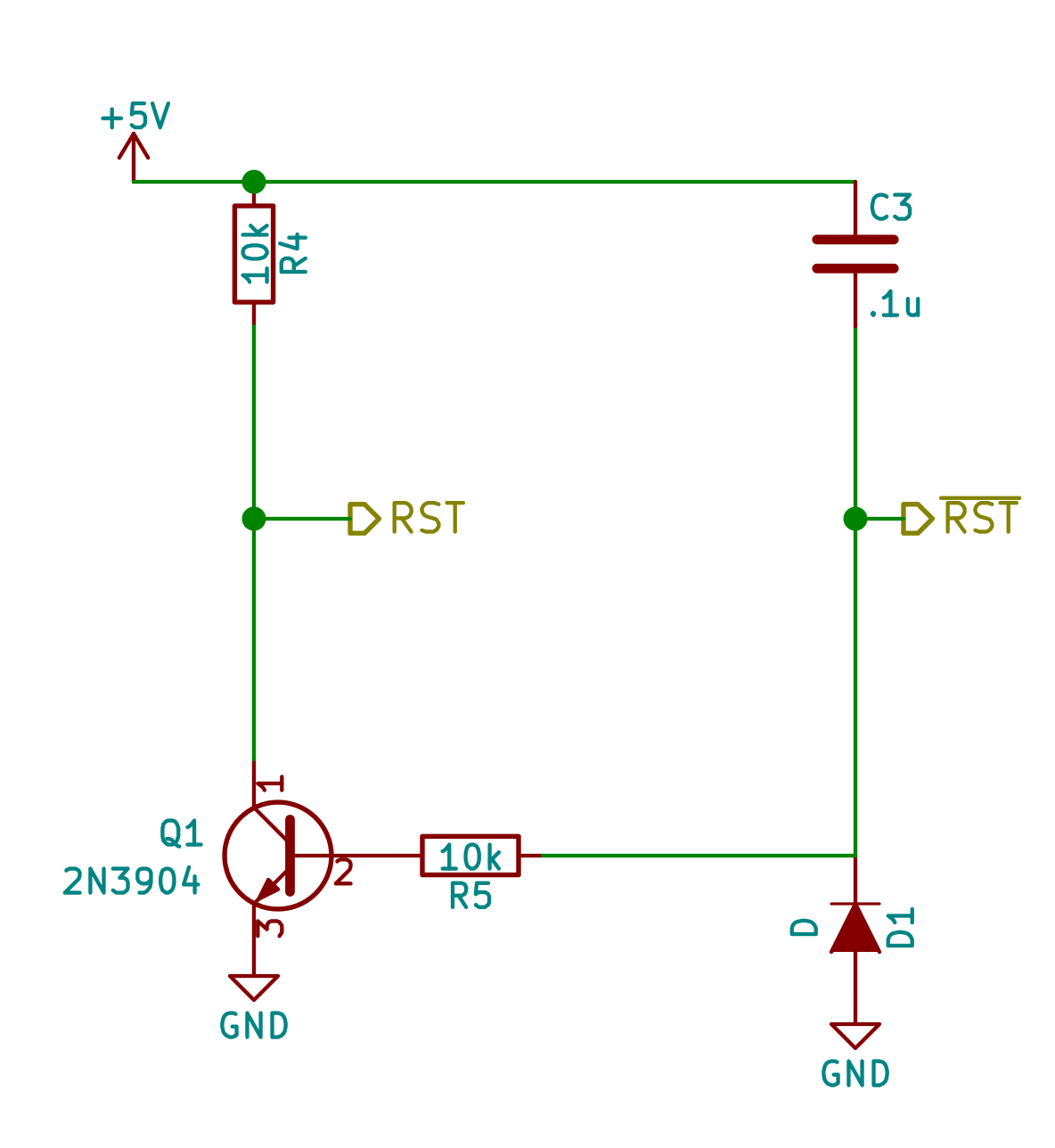
The goal of this circuit is to apply a LOW value to the reset pins of the 555-timer and each of the counter ICs for a brief period when power is initially applied to the system. After a short time has passed the value should change to a HIGH value so the timer and counters will start working from a zero state.
One problem I encountered was a requirement to trigger the counter reset pins from both the power-on reset signal and the Q= signal. To solve this problem I needed the power-on reset circuit to also generate an inverted reset signal. This signal would start HIGH and transition to LOW once the system initialized.
This circuit is basically an RC charging circuit connected to a transistor. When power is initially supplied C3 will begin charging through R5 and Q1. This charging will take a small amount of time, during which Q1 will be switched on. While Q1 is on the RST output will be low as the current will flow through Q1 to ground instead. A small amount of current will also be driven through RST resulting in it having a HIGH value initially and quickly drop to LOW as the capacitor charges and the current is reduced.
Once the capacitor is charged Q1 will turn off and disable that path to ground resulting in current having to go through RST which will drive it HIGH. At the same time little to no current will be traveling through the capacitor causing RST to be pulled LOW.
I simulated the circuit with LTSpice to get an idea of the timing with different resistor and capacitor values. With the values shown RST will be LOW for about 10ms at which point it will climb HIGH and enable the clock. RST will be HIGH for about 0.6ms, quickly dropping to a LOW value and enabling the counters. Even though the HIGH time on RST is very short it is enough time to clear out the counters and get them ready for when the clock starts a few milliseconds later.
1Hz 555-Timer Circuit
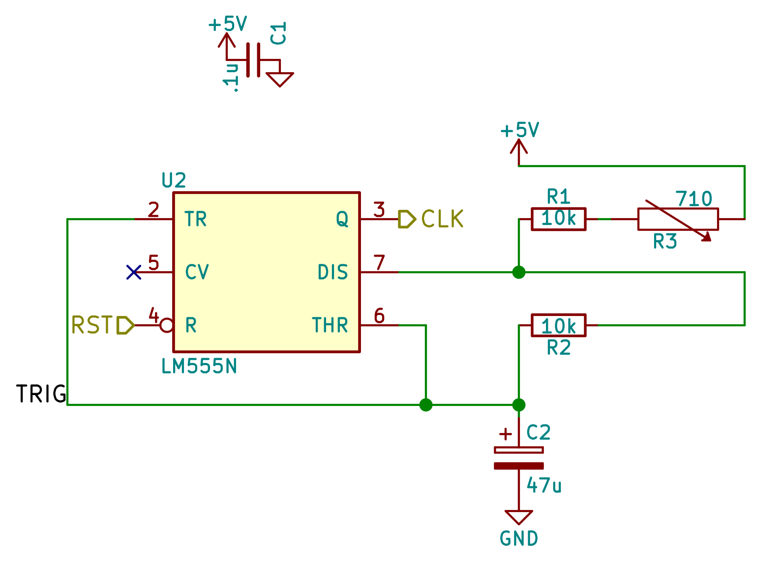
This is pretty much just your standard astable 555 oscillator circuit. In order to account for resistor tolerance issues I decided to split R1 into a 10kΩ resistor and a 1kΩ adjustable resistor. That would allow me to make small tweaks and get as close to the 10.71kΩ as possible.
Second counter
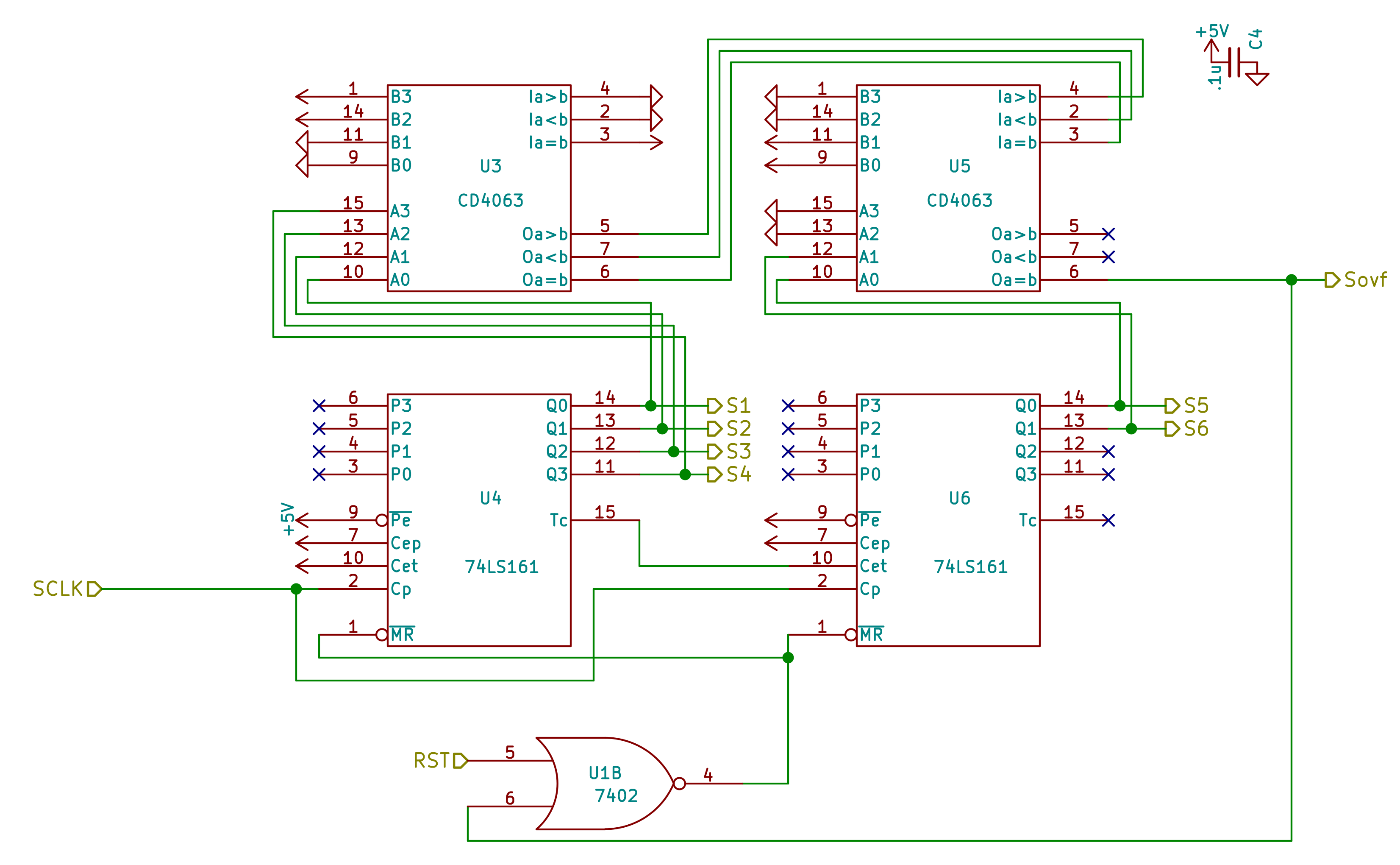
Next was the circuit for counting the seconds. This would take the clock signal generated by the 555-timer circuit and use it to increment the 4-bit counter every second. The full seconds range of 0-59 requires 6-bits total so two of the 4-bit counters are necessary.
As the counters increment the signal is feed into two 4-bit comparators which are programmed to detect when the counters reach 60. When 60 is detected these comparators trigger a reset of the counter IC's taking them both back to zero.
In order to reset the counters it is necessary to apply a LOW signal to their MR pins. Since the output of the Q= pin is HIGH when the reset needs to occur it is necessary to invert this signal. The MR pin also needed to be tied into the power-on reset circuit so that the counters are initialized to zero. By inverting the power-on reset signal (using RST) we then have a simple condition for resetting the counters: Reset when either Q= is high or RST is high by putting a LOW on the MR pin. This condition is easily solved with a NOR gate.
The Q= output is also fed into the minutes stage as it's clock signal. This causes the minutes to increment each time the seconds reaches 60.
Minute counter
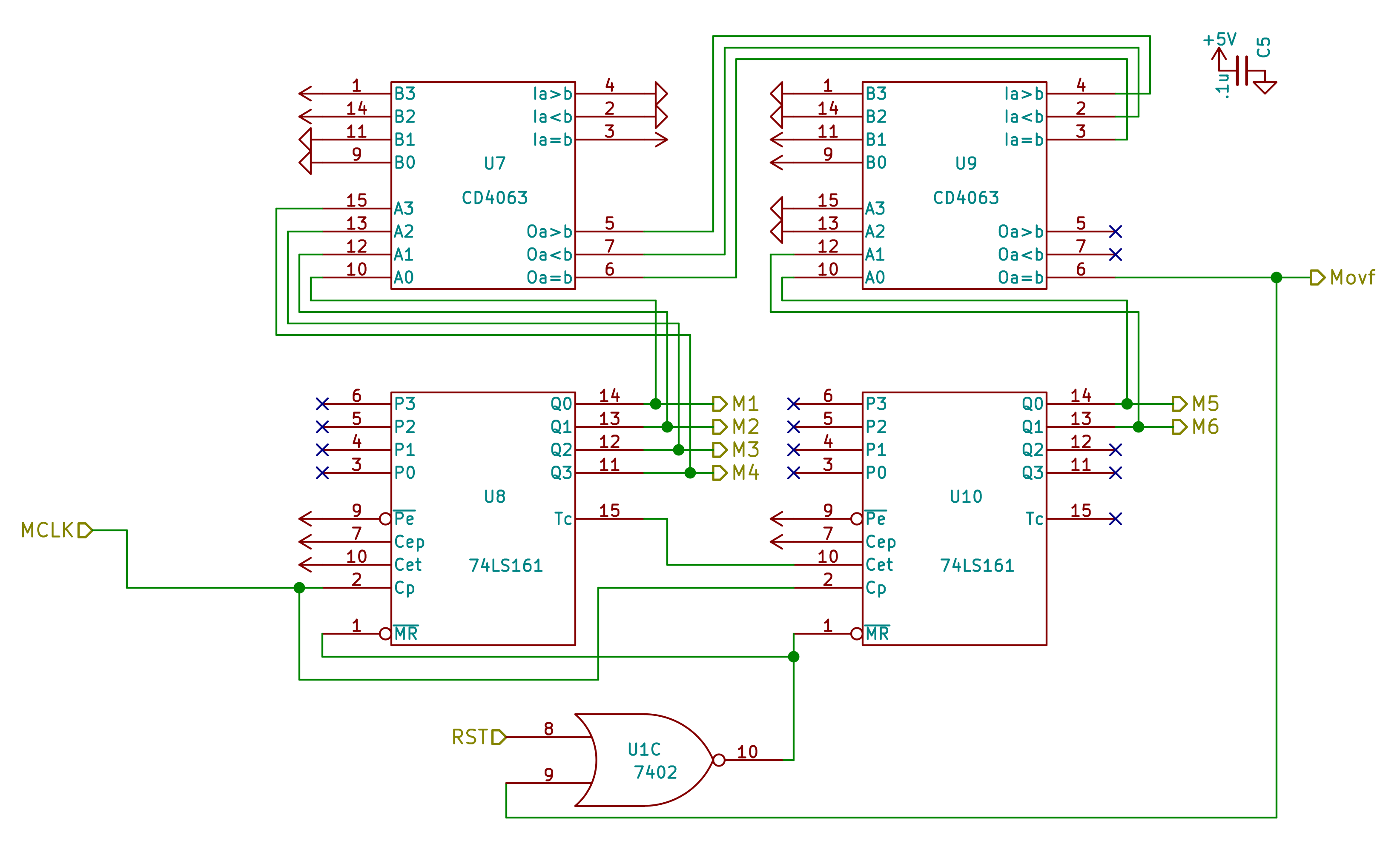
The minute counting circuit is essentially a copy of the second counter circuit with a few minor adjustments. The minute clock comes from the seconds rather than the timer, and it outputs a signal for the hours clock. Other than that they are identical.
Hour counter
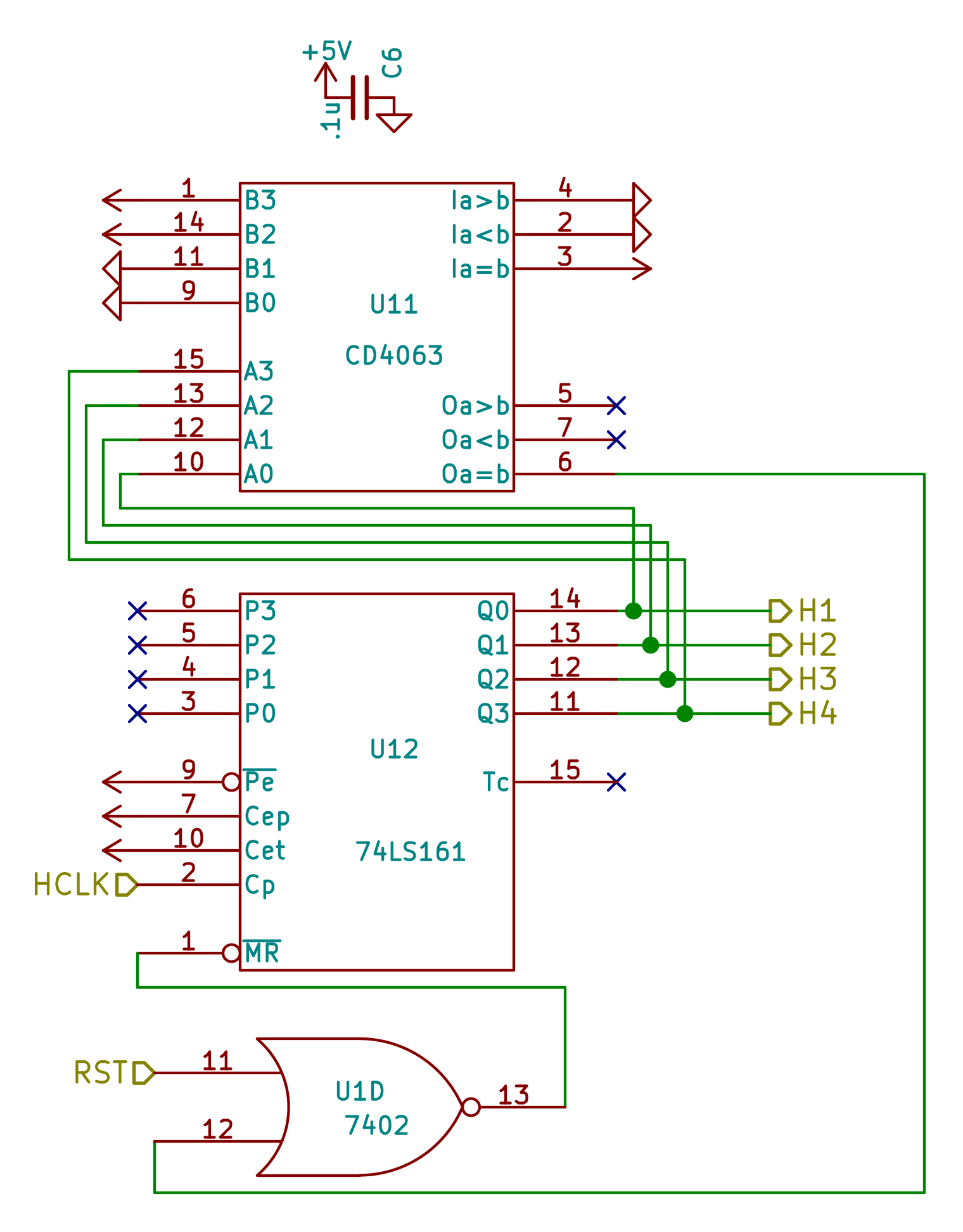
Finally, the hour counting circuit is a bit simpler. I chose to do a 12-hour clock as that will fit within 4-bits meaning only a single counter and comparator IC is required. The comparator IC is configured to detect when the counter reaches 12 and reset it to 0.
Tying it all together
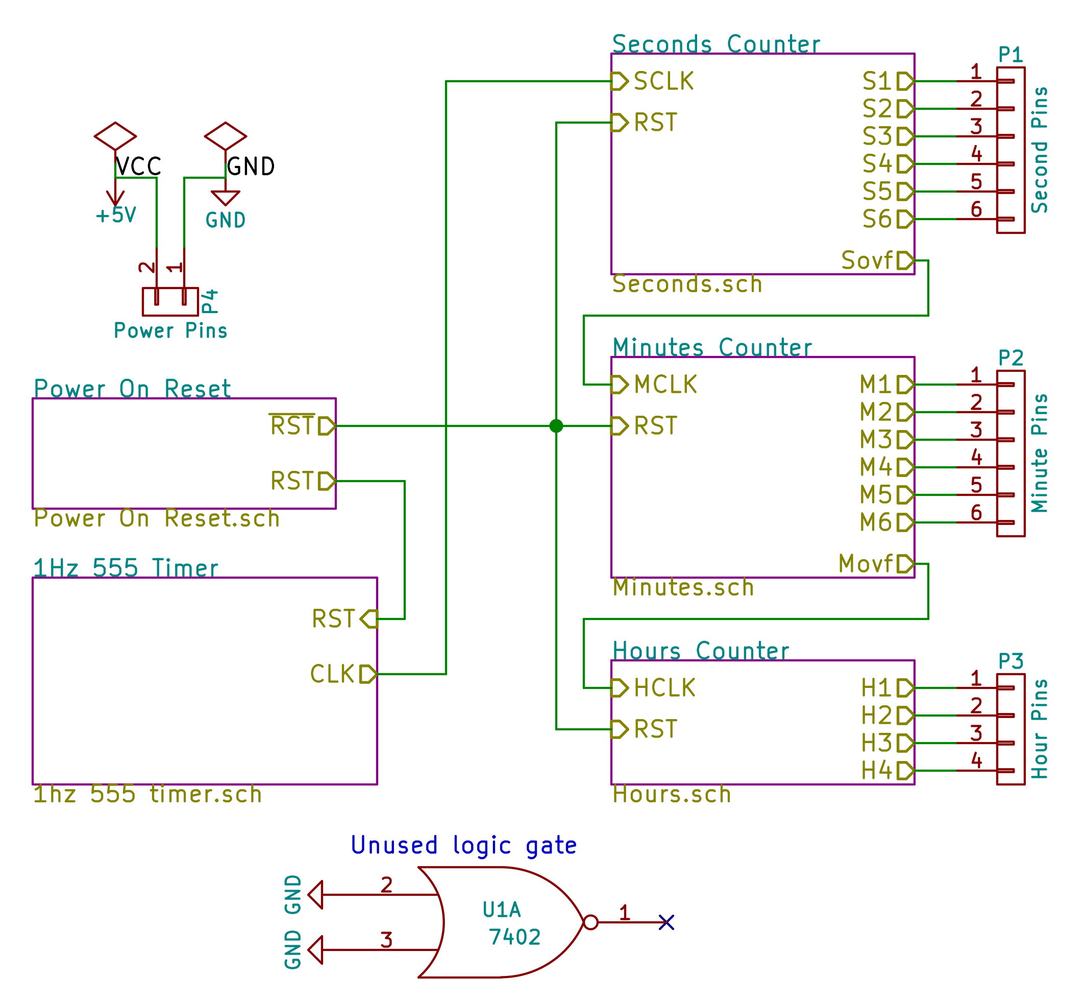
I tied all the sub-circuits together and fed the individual bit outputs to pin connectors which could then be connected to LEDs. The counter chips are rated for 20mA output current which is plenty to connect directly to a resistor and LED. If more current were needed one could instead connect to the base of a transistor to drive a higher power output.
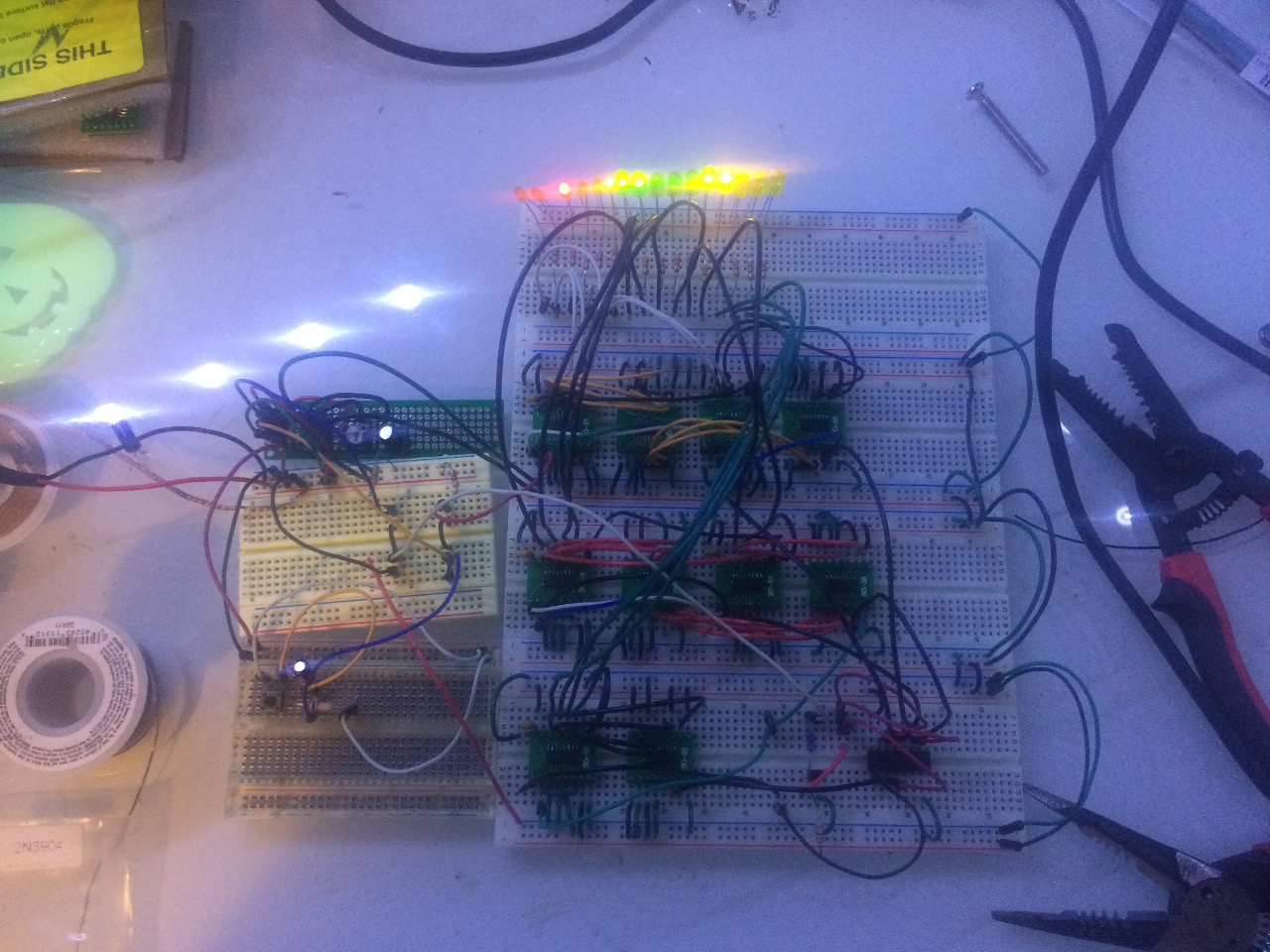
Testing it out
Admittedly, the above schematic isn't actually the one I started with. My initial schematic had a few flaws which I found when testing the circuit on some breadboards. For example, I initially tried to use the loading capability of the counters to reset them rather than the reset pin but discovered that did not work as I had thought.
So far I've been running the above schematic on my breadboard for a while now without and real issues. The timing is a bit off but that should be a matter of adjusting the resistors and not a major problem.
Eventually I plan to create a PCB design of this and order a few though OSHPark. When I get that done and am happy with the result I'll post an update about that.
Update (March 17, 2017)
I did a PCB layout for this project and had some boards made through OSHPark. After assembling them and trying my hardest to get the clock signal as accurate as possible the best I could do was a signal that was about 4 seconds per minute fast. If I started a timer and the clock at the same time the clock would reach one minute when the timer was only at 56 seconds.
I knew going into this project that accuracy was a problem but had hoped by including some adjustable resistors I could get it close to right. Such a thing might be possible if one used higher precision resistors/caps and spent more time tweaking, but I do not think it's really worth the effort.
I've decided that these boards will just be more of a toy item that acts like a clock but is not one. They still make for decent wall/desk widgets. I'll be working on updating this schematic with a more accurate clock source in the future.